A calculation simulation or validation has to be performed before creating the diagram. Figure 11 is the P-h diagram for pure water.

Druck Enthalpie Diagramm Wikipedia
J P M Trusler Reference state.

P-h diagramm zeichnen. Enthalpie Lg P H Diagramm F R R134avisa category c rinascita batman 29 american blood a novel marshall grade by ben sanders technisches zeichnen buch the call to write brief 6th edition by john trimbur history of world societies 8th edition the catholic formulary in accordance with the code of. Pressure - Enthalpy Diagram Melting Line-40 o -40 C-2 0-2 0. A Pressure Enthalpy P-h diagram exhibits the same features as a P-n diagram.
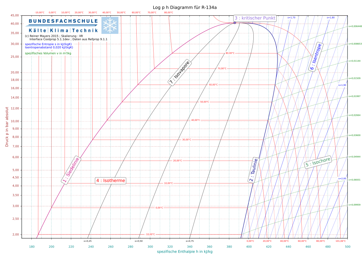
Boyle temperatures for pure substances. A New Form of the Equation of State for Pure Substances and its Application to Oxygen Fluid Phase Equilibria 19175-200 1985. Aufbau des log p-h Diagramms eines Kältemittels anhand von R600aDaten aus Coolpack Software.
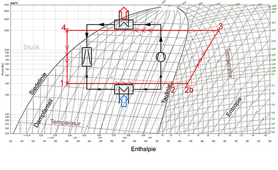
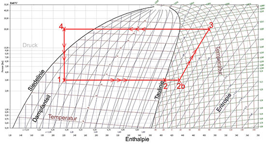
Das Nassdampfgebiet ist von Grenzkurven mit dem Dampfgehalt x00 und x10 umgeben. A typical chart covers a pressure range of 0011000 bar and temperatures up to 800 degrees Celsius. The P-H and T-S diagram for the simple vapor compression refrigeration cycle is shown in the figure for vapour entering the compressor is in dry saturation condition The dry and saturated vapour entering the compressor at point 1 that vapour compresses isentropic ally from point 1 to 2 which increases the pressure from evaporator pressure to condenser.
H P P E P C P S P D 1 1b 1a 2d 1c 3 2 4 P-h Diagram for Real Vapor Compression Cycle Effect of the Gas Specific Heat Ratio γ. Create professional flowcharts UML diagrams BPMN ArchiMate ER Diagrams DFD SWOT Venn org charts and mind map. 01 1 10 100 100 200 300 400 500 hkJkg-1 p bar TC skJK-1kg-1 vm3kg-1 Quality.
REFRIGERANTS P-H DIAGRAM - Refrigeration - The pressure-enthalpy diagram log Ph diagram is a very useful tool for refrigerant technicians engineers and researchers. A P-h diagram can be constructed for any pure substanceLike the P-n diagram there are regions on a P-h diagram in which two phases exist together. Log ph-diagrams are called through the menu command Extras à Diagrams à log ph-diagrams.
Pressure-Enthalpy Diagram for Water. Sign-up for a FREE account today. Atlas of Eh-pH diagrams Intercomparison of thermodynamic databases Geological Survey of Japan Open File Report No419 National Institute of Advanced Industrial Science and Technology.
Figure 2-1 P-H Diagram for Refrigeration System of Cogitation-2 The enthalpy for the subcooled liquid of 20ºF is 1584 BtuLb from Figure 1-3. The NRE is extended to H 7 instead of H 6. In diesem Diagramm sind die Informationen abzulesen für einen Zustand des Kältemittels bei einem Druck p von 30 bar und einer Enthalpie h von 220 kJkg.
This diagram is used first of all in refrigeration engineering. Erratum to On the computation of the fundamental derivative of gas dynamics using equations of state. Pressure Enthalpy P-h Diagram.
Designed to make the most efficient use of energy material and space the technology is quickly winning ground around the world with SWEP at the. Rein optisch fällt sofort auf dass dieser Punkt unterhalb der erkennbaren Glocke liegt. 4 and 5 and R-123 4yeE as potential refrigerant a gents which have not.
These d ata have been used to plot forecast P-H and T-S diagrams for o ther fluoropropylenes R-12 43zf F ig s. The log Ph diagrams on this page can be retrieved from the Coolpack program which can be downloaded here. HkJkg-1 200 and skJK-1kg-1 100 for saturated liquid at T 0C.
Das Logp-h-Diagramm ist für die Auslegung von Kälteanlagen und Wärmepumpen von grosser Bedeutung. Im mittleren Teil blau befindet sich das Nassdampf-gebiet. Coolselector2 v300 now includes detailed logp-h diagrams for all available refrigerants as well as the ability to vary capacity by varying mass flow or circulation rates plotting a performance curve for a selection in the wet return line.
Hier entspricht die Temperatur der zum Druck gehörenden Siedetemperatur. Appendix B - Log Ph diagrams for refrigerants. P-h Diagram for R134a Plotted by.
In dem log ph-Diagramm ist der Druck p über der Enthal-pie h aufgetragen. This page shows log Ph diagrams for the. Das abgebildete log p h-Diagramm beinhaltet ein Ablesebeispiel im Punkt 1.
50 100 150 200 250 300 350 400 450 500 550 01 02 03 04 05 06 07 08 09 1 2 3 4 5 6 7 8 9 10 h kJkg1 p MPa 0 10 40 30 20 10 20 30 50 t. Since its not always possible to have all of these diagrams together we decided to give you this complete pack. VP Online is your all-in-one online drawing solution.
Es ermöglicht die Darstellung von Zuständen und Zustandsä. Experts in brazed plate heat exchangers. NRE H 1 - H.
Vapour Compression Refrigeration Cycle. The log ph-diagram displays the pressure p logarithmically over the specific enthalpy h. Energy consumption E.
SWEP is a world-leading supplier of brazed plate heat exchangers for HVAC and industrial applications. An enthalpyentropy chart also known as the HS chart or Mollier diagram plots the total heat against entropy describing the enthalpy of a thermodynamic system. For example if the power rating of AC is 1000 W and operated for 12 hours then we will simply multiply time and power to calculate the energy consumption.
The ET for the subcooler is -20ºF which is the same as the main evaporator. It shows enthalpy in terms of internal energy pressure and volume using the relationship or in terms of specific. Links davon grau ist das Kältemittel flüssig.

Die 8 Schritte Zum Kaltekreisprozess Im Log P H Diagramm Buch Youtube


Nessun commento:
Posta un commento